Home Up FEEDBACK CONTENTS SEARCH


[Under Construction]

Home Up


Universal Pump Controller

Product Manual


Model : M3


Issue Date : 08/11/08


Prepared by: E. Medina


Last Revision date : 08/11/08


INDEX


1. OBJECTIVE:

The purpose of this document is to inform the user about the design and specifications of the M3 Pump Controller for its proper use.


2. SPECIFICATIIONS:

2.1. GENERAL DESCRIPTION:

The M3 is a pump controllers that will control 1, 2, or 3 pumps. It is designed to work on systems with floats or analog level sensors.


2.2. OPERATION MODES

When using floats, the operating modes are Alternator and Fixed Sequence.

Alternator Sequence alternates the pump that starts, and the Fixed Sequence has the same pump starting every time.

For the Alternate Sequence there are two variations, the first one is First On

First Off (FOFO). This variation powers on one pump, then the second pump, and after the third one, and turns them of the same way, beginning with the one that

Powered on first, followed by the second to power on, and ending with the last pump to power on. The next time that a pump needs to start, it will start the pump that started as second the previous time, followed by the third pump to start, and ending the first pump to start.

The second variation of the alternate Sequence is the typical. This variation alternates the starting pump every time after a complete cycle. The difference between the FOFO and the typical sequence is that the typical will stop all the pumps at the same time once it reaches a stable level.

The Fixed Sequence does not alternate the starting pump. It will always start with the same pump, and it will power off all the pumps at the same time once it reaches a stable level.

When using analog signals the operating modes are signal scale, fixed Sequence, Alternator typical, and Alternator FOFO.


2.3. GENERAL SPECIFICATIONS:

The Universal Pump Controller (UPC) is contained in an enclosure 10" X 8" X 6". The UPC is composed by the following parts.

2.3.1. PLC

The M3 computes the different algorithms from Analog and Digital inputs. The PLC has 12 Digital Inputs, 4 Analog Inputs and 6 digital output relays.

To operate, the controller uses 12VDC/24VDC.

For communication it uses an RJ45 port.

The PLC has a display screen with 20 buttons that will enable the user to interact with the system.

2.3.2. M3

The PLC is connected to a board, which with the use of a max 232 chip, it is able to convert from RS232 to TTL and backwards. It also a modem that enables the controller to give a feedback to the user.

2.3.3.  MODEM

The M3 uses the AR200 modem to communicate to cell phones or emails through the pager network.

2.3.4. BATTERY


The system uses a 12 VDC battery to operate the Controller, and through a voltage regulator there is a voltage drop to operate the Modem at 5VDC.

2.3.5. BATTERY BACK-UP


The system has a charger that will keep the battery charged in case of an emergency where there is no electricity.


3. GENERAL INFORMATION

The Controller is built to interact with the user through the use of 20 keys that are located in the front of the PLC. From this 20 keys 10 are shared as number and function keys. Also it has 4 arrow keys and an enter button that will let the user move through and edit the inside screen, when it is enabled. It also brings 4 auxiliary keys and an escape (ESC) button that enable the user to move through the screens.


When it is possible to enter a selection, the controller will display an arrow pointing to the Auxiliary key that will enter the selection.

For example in this screen the possible selections are Control and Modem. To select Control you must press the upper right key, and to select Modem you must press the lower left key. If the user presses the lower right or upper left key, the controller will not select anything because the buttons have been disabled.

If it is possible to use the arrows, numbers, or function keys in an specific screen, the manual will let the user know.


4. DESCRIPTION OF SETTINGS

In this section we cover the operation of each sequence and a brief description of the way each sequence works.

4.1. ANALOG

4.1.1. FIXED SEQUENCE

Fixed Sequence is a setup for an analog pump system of two or three pumps. The sequence that it follows is always the same, starting with one pump, followed by a second, and ending by the last pump. Once it reaches the level of stop, the pumps will begin stopping in a reverse order from the way they started, beginning by the last and ending by the first to start pump.


4.1.2. ALTERNATE SEQUENCE

Alternate Sequence is a setup for an analog pump system of two or three pumps. The sequence that it follows is always different, because it will vary the pump that starts in a given sequence.

4.1.2.1. TYPICAL ALTERNATE SEQUENCE

Typical Alternate Sequence alternates the starting every time that the pump is called to start, and all the pumps that are called to start will remain on until the level where the system is set to stop is reached. There, all pumps will stop simultaneously.

4.1.2.2. FOFO ALTERNATE SEQUENCE

FOFO Alternate Sequence alternates the starting pump every time that the pump is called to start, and when a pump is set to stop, the pump that started first will stop first, followed by the second to start pump.


4.2. FLOAT

4.2.1. FIXED SEQUENCE

Fixed Sequence is a setup for a float pump system of two or three pumps. The sequence that it follows is always the same, starting with one pump, followed by a second, and ending by the last pump. Once it reaches the level of stop, the pumps will begin stopping in a reverse order from the way they started, beginning by the last and ending by the first to start pump.


4.2.2. ALTERNATE SEQUENCE

4.2.2.1. TYPICAL ALTERNATE SEQUENCE

Typical Alternate Sequence alternates the starting every time that the pump is called to start, and all the pumps that are called to start will remain on until the Stop level has been reached. There, all pumps will stop simultaneously.

4.2.2.2. FOFO ALTERNATE SEQUENCE

FOFO Alternate Sequence alternates the starting pump every time that the pump is called to start, and when the a pump is set to stop, the pump that started first will stop first, followed by the second pump.

4.3. VARIATIONS

One of the variations that we have set is the use of two pumps in a three pump system. The three pumps will alternate according to the sequence they are working in, as in any regular sequence, but the difference is that the system will never have three pumps running at the same time.


5. CONTROL

After powering on the UPC, the main screen will appear. This screen will show two options, Modem and Control; by clicking on the control button we access the Controllers controls settings.


5.1. ANALOG OR FLOAT(DIGITAL)

After entering the controls Menu, you will have two new options, Analog and Float. Select the one that describes the type of level sensor that your system is equipped with, or the one that best suits your system.

5.2. FLOAT

An F on the upper left of the screen will let you know that the menu corresponds the settings for floats systems.

5.2.1. 1, 2, OR 3 PUMPS

After selecting the type of Floats as the type of signal of your system, the screen will ask for the number of pumps that the user’s system has. In the upper right it will show the option for 3 pumps, in the lower left it will show the option for 2 pumps, and in the lower right the option for 1 pump.

5.2.2. ALTERNATOR OR FIXED SEQUENCE (2 or 3 PUMPS ONLY)

An F _XP on the upper left of the screen will let you know that the menu corresponds the settings for floats systems with X number of pumps.


After selecting the number of pumps you are going to be working with, a new screen will appear. In this screen we will be asked if we want the pumps to alternate the sequence in which they turn on and off or if we want it to be a fixed sequence. For our convenience we keep using the screen for a 3 pump system.


5.2.2.1. ALTERNATOR SEQUENCE

An F_XP_A on the upper left of the screen will let you know that the menu corresponds the settings for floats systems with X number of pumps with an Alternating sequence.

Once you have selected the option for Alternate Sequence, a new screen will appear, showing the options of Typical and FOFO (First On First Off). To select the alternation mode that would best fit your system, just press the corresponding button.

5.2.2.2. FIXED SEQUENCE

5.2.2.2.1. TWO PUMP FIXED SEQUENCE

Once you have selected the option for Fixed Sequence, you will be asked to select the number of the pump that will be established as lead and the one for lag.


5.2.2.2.2. THREE PUMP FIXED SEQUENCE

Fixed Sequence, you will be asked to select the number of the pump that will be established as the lead pump.


5.3. ANALOG

An A on the upper left of the screen will let you know that the menu corresponds the settings for Analog systems.

5.3.1. 1, 2, OR 3 PUMPS

After selecting the type Analog as the type of signal of your system, the screen will ask for the number of pumps that the user’s system has. In the upper right it will show the option for 3 pumps, in the lower left it will show the option for 2 pumps, and in the lower right the option for 1 pump.

5.3.2. Signal Scale

Before selecting the type of sequence to be working with, the user has to scale the analog signal so that the controllers interprets the maximum, minimum, stop, lead, lag, and lag-lag levels according to the strength of the signal it receives. For this you have to press the auxiliary button that is located on the upper right.

Then, you will be asked for the maximum and minimum levels, and if you select the option on the upper right, config, you would be asked to configure the Stop, lead, lag, and lag-lag levels. In order to configure these options, you will have to use the arrows to move through the different options, the ENTER button to select the option to be edited, the Numbers to select the desired number, and the enter button once again to accept your entry.

5.3.3. ALTERNATOR OR FIXED SEQUENCE (2 or 3 PUMPS ONLY)

An A _XP on the upper left of the screen will let you know that the menu corresponds the settings for floats systems with X number of pumps.


After selecting the number of pumps you have scaled the analog signal you will need to select the type of sequence you are going to be working with. In this screen the user will be asked if he wants the pumps to alternate the sequence in which they turn on and off or if he wants it to be a fixed sequence. For our convenience we keep using the setup for a 3pump system.


5.3.3.1. ALTERNATOR SEQUENCE

An A_XP_A on the upper left of the screen will let you know that the menu corresponds the settings for floats systems with X number of pumps with an Alternating sequence.

Once you have selected the option for Alternate Sequence, a new screen will appear, showing the options of Typical and FOFO (First On First Off). To select the alternation mode that would best fit your system, just press the corresponding button.

5.3.3.2. FIXED SEQUENCE

5.3.3.2.1. TWO PUMP FIXED SEQUENCE

Once you have selected the option for Fixed Sequence, you will be asked to select the number of the pump that will be established as lead and the one for lag.


5.3.3.2.2. THREE PUMP FIXED SEQUENCE

Once you have selected the option for Fixed Sequence, you will be asked to select the number of the pump that will be established as the lead pump.


6. OPERATION OF STATION

This section will provide the user the knowledge to operate and monitor the use of the controller in the station.

6.1. COMMON SETUP AND PARAMETERS

Once the user has selected the appropriate system that best describes his needs, the controller will display a new screen with the options of this setup. One of the options will say Control On or Off. This option starts or stops the setting that the user has selected. If ON is displayed, it means that the current setting is running, but if OFF is displayed in means that the setting is OFF.

The othercommon option is the parameter. Once this option is selected, a new screen will be displayed. In this new screen there will be four new options.


Hourmeter: Hourmeter is the option that keeps track of the amount of times that each pump has started and the amount of time it has ran. The time is displayed in hours. Inside each pump, there is a reset button, which resets the counters if pressed.

Delay: The Delay parameter will set the time or period for waiting before the level or pump will activate. This time helps the user to set the accuracy of the system to fit his needs. Increasing the time will


increase the accuracy because the oscillation of the level of the water will affect the system less.

Lead, Lag, and Lag-Lag will prolong the time for pump to start once it reaches the corresponding level.

On and Off Delay will prolong the time for the pump to initialize and to stop.


Restart: This option is used whenever there is a pump failure and the pump stops running. When a failure occurs, if the pump is set in Auto, the pump will resume its work the next cycle when it is called if the failure has been corrected. If the option is set in Hand, the operator will have to manually enable the pump once the failure has been fixed.


The third common option that is displayed is Next. Pressing this button will display a new screen with the new options Modem, System, and Alarms.


The System option will display a screen with all the pumps in the system, for our convenience we have selected a 3 pump float system. This screen will mark the pumps that are running and also the level at which the water stands. In the setup for the FOFO, after pressing the button for next, a screen with the options of Alarm and system will be displayed. Pressing the option of System will display the monitor screen.

If the controller is set for a float system it will display the different levels of the floats, marking the floats that are on, and leaving blank the ones that are not active.
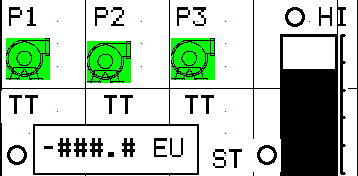
 

If the system is set for an analog system, a bar will be displayed on the right of the screen that will mark the level of the water.
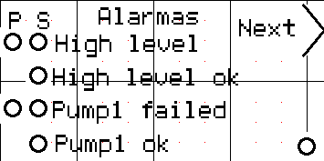
 

The Alarm option will display a screen with the status of the different alarms of the system. There will be a Next Button that will display the next screen. Pressing the ESC button will go back to the previous screen. Some of the different alarms have to options P or S. P means that the alarm is active and S that the system is sending a message. There is also a dot displayed in the lower left corner. This dot displays the status of the Modem (Online if black, Offline if white, and Busy if blinking).

The Modem Option will send you to the Modem Menu from the Main screen. (Please see section 7 MODEM)
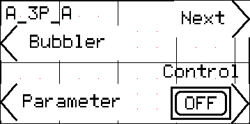


In a Analog System there is also an option named bubbler. This option works with the use of a compressor. To active this system, go into bubbler and then press the ON button. To purge the system the user has to enter the bubbler menu and then enter the Pur button. Select the time of purge by selecting enter, followed by the time the user wants to purge, and then press the enter button again In the menu there will be a ON/OFF button for the compressor and an ON/OFF for the valve. This menu will also display the compressor’s air pressure.

6.2. MONITOR THE SYSTEM


In a One pump system there are no Alternator or Fixed Sequences given that there is only one pump. Pressing the button of the control ON or OFF will start or stop the system.

For regular monitoring of the system, the display should be left on the Pump Monitor Screen. For this, the user has to press the next button followed by the system button.

For monitoring of the alarms the user has to press the next button followed by the alarms button.

For the options of the Modem, the user has to press the Next option followed by the Modem button.

To track the amount of times that the pump has started and the amount of time it has been running the user has to go into parameters and then into hourmeter. Select Pump # of the pump that the user wants to check.


7. MODEM

In the main screen there are two options, Control and Modem. If the Modem button is pressed it will display the following option:


7.1. HELP

F1 RESET: This option cleans all the variables and communications. This option will also reset the system’s communication in case that the communication fails at any given time.

F2 TX MSG: This option when pressed sends a Text message with the System Status.

F4 GET STATUS: When pressing the F4 button, the controller will refresh the screen. This feature works only for the Text Message and Modem’s Status menus.

7.2. CONFIG

This option enables the user to edit the name for which the pump station will be recognized as when the messages are received. It also let’s the user edit message that will be displayed when there is an specific alarm that is an extra alarm that the user can configure for an specific need.

7.2.1. TITLE 1

Title 1 is the First Name of the Controller. This name will be displayed on every text message that the controller sends.

7.2.2. TITLE 2

Title 2 is the Last Name of the Controller. This name will be displayed on every text message that the controller sends.

7.2.3. cAlarm on

cAlarm on

7.2.4. cAlarm off

cAlarm off


7.3. TX MSG

Recv EOT-NAK: 1504 NAK

Recv ACK: 06

Recv ACK: 06

7.4. STATUS

This section indicates the status of the communication of the controller. The three different categories that are checked are Out of Range, Busy, and Registration. The controller displays 49 if the status is set, and 48 if it is not set. If it shows a different number, there is a problem.

Out of Range

Out of range indicates if the controller receives a signal or not. If it shows 49 that means that it has established a connection with a tower, but if it shows 48 that means that it is currently working on locating a tower and establishing a connection with it. If it takes too long searching for a signal, it can be assumed that there are no signals in that location.

Busy

This status shows if the controller is sending or trying to send a message. This option has no connection with the other two since it can be sending a message when connected or trying to send one without connection. If the status shows 49, it means that there is a message been sent, and if it shows 48 it means that there is no message in process.

Registration

Registration is the status that indicates if the controller has established a connection with a tower. If it shows 49 that means that the system is Online, and if it shows 48 that means that the system is Offline.


** If at any point the statuses of registration and out of range are both on 48 or 49, there is a technical problem.


8. MESSAGING

8.1. OUTGOING

The controller uses GSM messages that reach the users via text messaging or email. The user receives a message when there is a problem in the system, when the system responds normally after a problem has been detected, and when the system is scheduled to report its status.

Depending on the type of error that the system encountered, the controller will send the corresponding message.

Pump # fail

When the system restores or corrects a problem it will the corresponding message.

System OK

Pump # OK

Also the following message can appear:

Bad command

8.2. INCOMING

The controller has been programmed such that it will receive instructions through the messaging system. Some commands that the system recognizes are

TEST: Test will order the controller to send a text message with the in formation of each pump’s run time and the stations status. The display is:

TITLE 1

TITLE 2

SYSTEM OK

P1 =0000.0HRS S=0004

P2 =0000.1HRS S=0004

P3 =0000.0HRS S=0004

Any other command not shown in our list: The system will return a message displaying Bad Command if it received a command that it does not recognize.


8.3. TROUBLESHOOTING

If the system has a failure and stops working, but doesn’t return to normal operation once the failure has been fixed, go into Parameter/ Restart/ Pump # and enable the Hand option. This means that the system is set to be checked manually before resuming regular work. The user can set the system to be Automatic by pressing in the button corresponding to the Auto Option.


HOLD F10 for 3s


Send mail to raul@cellunetics.com with questions or comments about this web site.
Last modified: September 20, 2011